You must know how to output data and read input ports of microcontroller,If you know how to do, you can skip this step
We will work with ATMEL AVR microcontroller and codeVision AVR programmer which depends on C programming language, but the main concept applies to any microcontroller type and any programmer with any programming language, only syntax differs between a programmer to another.
Setting ports as inputs or outputs:
* For using any I/O port, we must first specify the Data Direction of ports or pins of ports ,because any pin can not be used as input and output at the same moment.
Any microcontroller has several ports with several pins for each, the number of pins for each port is often (not always) 8 pins. Data direction (In ot Out) of each pin in the port can be determined by a register called DDR.
Data Direction Register of Port A is shown above,each pin is represented by one bit,if the bin is required to be used as input,the corresponding bit is set to 0. If we want to output data on it,the corresponding bit is set to 1.
This is the rule of ATMEL AVR microcontrollers and can differ from other types of microcontrollers, so, you may find in other types that 1 represents Input and 0 output.
Now, we can specifiy which pins are inputs and whcich are outputs,for example, if we want pins from 0 to 4 to be used as inputs and from 5 to 7 as outputs we may write the following line ine CodeVision AVR:
or:
or:
if you used the code wizard, CodeVision would write this line for you.
You must have noticed that the letter 'A' in DDRA refers to port A, hence, if we are working with port B,we will specifiy values of Data Direction Register of port B which is called DDRB.
Again,names of Data Direction Registers are not the same for all microcontrollers, for example, you may find PORT0,PORT1, and PORT2 in some types instead of PORTA,PORTB, and PORTC in AVR microcontrollers.
How to input/output data from/to port:
To input data from port,this port or the required pins only must be first set as input port or input pins.Assume we want to receive data on port B,we first set it as input port:
DDRB = 0x00;
then we must prepare a variable to store the input data:
unsigned char rdata;
then data is simply transferred to the variable:
rdata = PINB; //transfer data from port B to variable rdata;
the word PIN is used for the whole port,not for one pin, but it is named PIN to differ from the word PORT wich is used for output:
PORTB = rdata; //output data stored in rdata to port B
if we want to read one bit we use '.' :
if(PORTB.00)
body
PORTB |= 0x01; //set the first bit of port B (PORTB.0)
PORTB &= 0xFD; //clear the second bit of port B (PORTB.1)
If you are familiar with C programming language, you fill find it easy to work with in embedded systems programming, you can refer to CodeVision AVR to find all functions available in the program.
Creating a small project using CodeVisionAVR:
1. Open CodeVisionAVR
3. Choose Project and click OK.
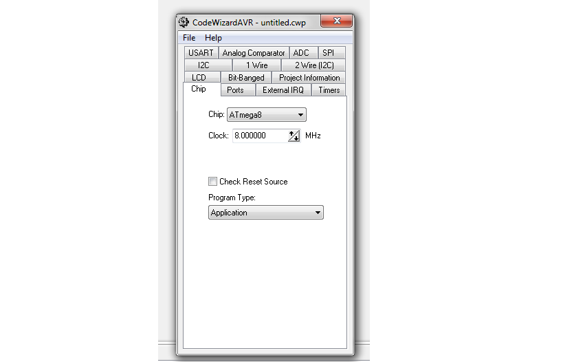
4. The program will ask you if want to use CodeWizardAVR, hit yes
6.Under 'Ports' tap select PORTB, This tab shows all available ports and the number of pins in each port, you may notice that there are only 3 ports in this chip and port C has only 7 pins
7. A toggle button resides next to each pin to determine Data Direction of this pin, switch the button next to Bit 0 to 'out'
8. Another toggle button is found,this button has two functions, one for input pins and another for output pins
Input pins:
T ; Tri-state --> This pin has three states (HIGH, LOW, and high impedance)
high impedance makes float pins acts as open circuit (neither HIGH nor LOW)
P : Pull up --> pull up resistor pulls the pin to HIGH state if no input is applied to it
output pins:
1: The initial state of the pin is HIGH
Now, make Bit 0 of port B output pin with initial state 1
Bit 0 Out 1 Bit 0
9. Select 'Ggenerate,Save, annd Exit' from 'File' menu
10. Type 'led_flash' as the name of the C source file,project name, and CodeWizardAVR file name as requisted.
10. Scroll down, and just below '// Place your code here' type in the following code:
delay_ms(500);
PORTB &= 0xFE;
delay_ms(500);
PORTB |= (0x01);
delay_ms() is a funnction provided by CodeVisionAVR and requires including a header file called 'delay.h', so scroll up and add the followinng line just after '#include <mega8.h>':
#includde<delay.h>
Now, microcontroller is ready to flash the led connected to pin 0 of port B.
Simulating results:
The most suitable simulation program is proteus, the latest version of proteus can be downloaded from here (Demo)


:max_bytes(150000):strip_icc()/003-import-a-color-palette-into-inkscape-1701897-f99f8fa7a4fe4f4ab20c109d89cf1dd6.jpg)
